DIY 108 Chassis Sub-frame Mounts
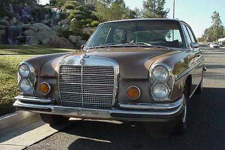
1973 280SEL 4.5
PeachParts would like to thank Shop Forum Senior Member, Mike Tangas, for contributing the text and pictures for this excellent Do-It-Yourself article. If you have any questions or comments regarding this process, please post them in the Vintage Mercedes section of the Shop Forum. Mike will do his best to reply to you there.
Changing sub-frame mounts on 108/109/111/113
The Problem
My 1973 280SEL was emitting an irritating knock going over bumps in the road, the front end would wander (similar to an old straight axle when the king pins are shot), and it also felt as if the front wheels would sometimes shift when reversing direction. Finally during my last oil change I noticed that a piece, which connected between the front axle carrier and the frame had broken.
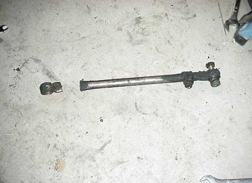
After asking several question, I learned this piece was the front axle stabilizer or lateral support rod. I discussed the broken rod with my local independent Tech, Franz. Franz explained that the stabilizer breaks like this when the front sub-frame mounts are bad. I was able to obtain a replacement stabilizer from a dismantler and I ordered a set of sub-mounts from Parts Shop.
Preparation - Safety First!
Once I had my parts I was ready to replace the sub-mounts...
"Deezel" Safety note: When working under a car supported on jack stands, have another adult party on hand who knows how to and is physically able to operate a floor jack. Also have a phone in the immediate area for your assistant to call 911 if the unthinkable should happen.
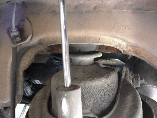
First, if you do not have access to a lift you will need to support the vehicle, off the ground at four points and level. Once the vehicle is securely positioned on the stands you are ready to proceed. Disconnect and remove the battery from the car. You will then need to disconnect the parking brake at the intermediate lever. Simply remove the cotter pin and lift the adjusting pin from the bracket. This will allow the parking brake cable to become slack. Remove the front wheels and place them under the frame, just behind the front wheel well (out of the way and extra safety margin should the stands fail). With the wheels removed you can clearly see the sub-mounts.
The Disassembly Process
Remove the shock absorbers, the stabilizer (lateral support rod) and brake lines. I drained the brake fluid into a clear glass jar, and quickly learned that the brake fluid had not been changed in many years and looked like old motor oil.
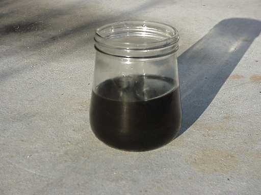
I decided to entirely drain the brake fluid, since I was already "in there". This is also a great time to inspect the front brake hoses for wear, age or deterioration and replace if necessary. The front brakes bleed out pretty quick once the lines are pulled, for the rear brakes, use a piece of rubber line and allow them to gravity bleed as you continue working at the front axle.
There are two short leaf springs, which provide longitudinal support of the front axle, these will also have to be removed from the frame, not the axle. Before removing the hex nuts, mark the position of the springs to the frame. The same nuts that hold the springs in place also hold the mounting brackets for the torsion bar. I probably could have left the torsion bar in place but decided to remove it from the vehicle.
You will also need to remove the battery tray to get access to all the mount bolts for the right hand mount.
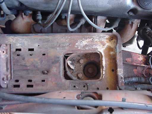
This is a great time to clean out umpteen years worth of crud, which has undoubtedly collected underneath. I even found a missing trim screw from the chrome grille on the cowling. :)
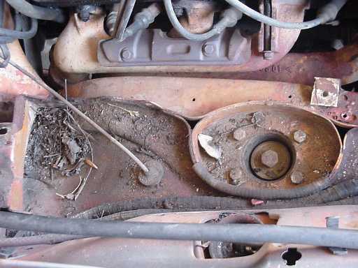
The large (19mm) bolt, surrounded by four smaller (13mm) bolts is the sub-frame mount attachment. The four smaller bolts hold the mount to the body, while the single large bolt holds the axle to the mount.
My M-B manual calls for loosening the hex bolts on the motor mount. Thanks to some sage advice from Steve Brotherton, this step is not necessary, but you do have to unbolt the top of the left side engine shock absorber and the fan shroud. By leaving the motor mounts connected, you can use the weight of the engine to lower the front axle carrier enough that only a little prying is required to get the old mounts out. There is just enough room to check the tightness of the motor mount bolts (19mm). I found that the left mount had loosened somewhat over the years.
At this point we are ready to loosen the sub-mounts and drop the axle, one side at a time. Place a floor jack under the lower control arm of the side you want to start with and raise the jack until the tension is taken off the mount. Loosen the large center bolt, once removed you can slowly lower the floor jack until the axle has dropped as far as it can. Next, remove the four smaller bolts holding the mount to the body. Now using a suitable lever, pry the axle away from the frame. By catching the lip of the upper mount recess and the top of the cup that the mount sits in, you can pry down and compress the coil spring, which creates enough room to remove the mount.
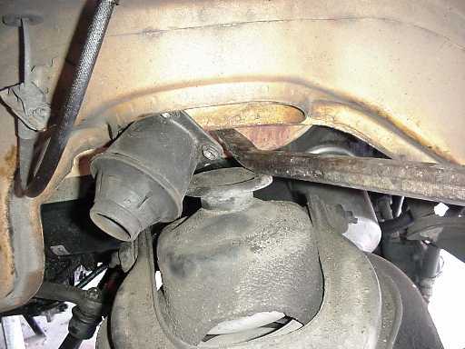
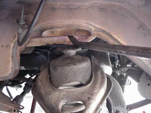
The Re-assembly Process
Once you have the old mount out, repeat the prying process and install the new mount. Once the mount is in place, I found it was easier to install the large attachment bolt first, then raise the axle until the mount almost touches the body. Now you can adjust the location of the mounting plate and align the four bolt holes.
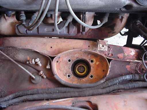
Install the four mounting bolts and snug everything up a little bit. Move the floor jack to the other side and repeat the process.
Once both mounts are in, torque the large attaching bolts to 10kpm (72ft lbs.) and the four mounting bolts to 2.5kpm (18ft lbs.). Locate spring to the frame and install the torsion bar (if removed), and snug the nuts up. Install the brake lines and shocks and loosely attach the stabilizer bar. The stabilizer bar has a split clamp, make sure the clamp is loose.
Once the car is lowered from the jack stands, you make final adjustments to the location of the leaf springs and torsion bar, the tighten the nuts, then torque to 12 kpm (87 ft lbs.), adjust the stabilizer bar and torque to 6 kpm (43 ft lbs).
Reattach the motor shock and fan shroud, and then bleed the brakes. Next install the battery tray and battery. Next stop - the alignment shop. You have successfully replaced the front sub-frame mounts.
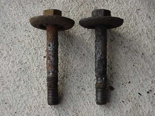
I found that my mounts were still intact, but the years had taken a toll on the rubber. The rubber had become very soft and flexible, which allowed the front axle to shift. It is this shifting that stressed the stabilizer bar to the breaking point, and caused the inner steel cone of the mount to rub on the attachment bolt.
Conclusion
The test drive revealed that the car pulls slightly right, not very much though. The alignment will take care of that. The front axle no longer "clunks" backing out of the driveway, or on hitting the bump at the intersection. I also could not detect any shifting of the front axle when changing direction. Once the alignment is done, I will be able to verify if the front end "wander" is also eliminated.
Since I have done all this work, I also decided to replace the steering dampener as well. I have ordered a new one from Fastlane, and will install as soon as it arrives.
Thank you to everyone here at the "Shop" for your assistance and advice.
- Mike Tangas 1/2001
CategoryDiy