Mercedes-Benz Driveability
Evaluating Electronic Engine Controls
by Steve Brotherton, Import Specialist
Published in: ImportCar, February 2001
Steve Brotherton is co-owner of Continental Imports, a 22-bay shop in Gainesville, FL, that employs 18 people, 10 of whom are technicians. A Bosch Authorized Service Center since 1986, the shop specializes in Mercedes-Benz, BMW, Porsche, Volvo, Saab, Jaguar, Honda and Acura. Brotherton has been an ASE-certified Master Technician since 1973 and is a recertified L1 specialist. In addition, he is a Bosch Certified Master Tech, president of the Alachua County ASA Chapter and member of the board for Florida ASA. He holds a bachelors degree in Metallurgical Engineering from the University of Florida. Steve is also a regular contributor to PeachParts's Shop Forum and currently moderates the Tech's Only forum.
When my wife's new ML320 had its "check engine" light come on with less than 15K on the speedometer, it was quite a job convincing her that she could drive the car until the dealer could fit her in 10 days later. I, of course, verified that the fault code indicated an O2 sensor problem and the risk was minimal to drive it around town another 10 days. I also evaluated the data stream to verify that the O2 sensor was functioning well enough so that the catalyst wouldn?t melt down in the meantime.
I have been working on cars for 30 years and now, more than ever, I see customers get in a panic over a small yellow light. These are the same people who often wouldn?t bring in their car when it was afflicted with other symptoms until it needed to be towed. This challenges technicians with the evaluation of a technical difficulty, with no external symptoms other than a small yellow light on the dash and whatever electronic self-diagnostics are available.In preparing to write this article, I talked to a number of technicians who answer Mercedes-Benz questions on the international Automotive Technicians? Network (iATN). They all said that the greatest number of questions being asked were still about CIS model cars. Most of these problems do have symptoms that are identifiable in the vehicle?s performance. While I use tools either listed as factory or cloned from such, I will demonstrate the simple ways to evaluate the electronic engine controls and make basic adjustments with common shop tools.Electronically, there are four windows to the KE-Jetronic System. Two of these windows involve self-diagnostic testing and fault codes. The other two involve dynamic monitoring of the two basic electronic servos. These are the electro-hydraulic actuator (EHA) and the idle control valve.
The first self-diagnostics were "real-time" only through fixed integrator duty cycles given on pin #3 of the diagnostic connector X11 (on the left fender). This value, that is normally read with Bosch?s Lambda closed-loop tester, KDJE-P600 (see Figure 5), can also be read with a good multimeter or scope on the duty-cycle setting.
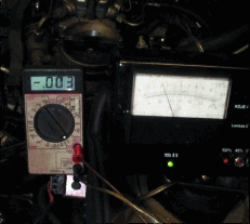
Figure 5: Factory tool reading of duty cycle and EHA current.
Patterns 1 and 2 (see Figures 1 & 2) indicate fixed whole number duty cycles, indicating a fault.
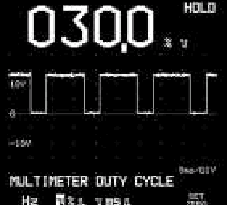
Figure 1: ECT sensor disconnected.
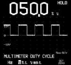
Figure 2: O2 sensor cold or disconnected.
Pattern 3 (see Figure 3) shows a closed-loop active reading that changes continuously and indicates the basic mixture. As the mixture is changed by the 3mm air flow plate trim screw, the amount of correction to achieve lambda is indicated by the integrator value. The value of 38% indicates a rich reading. The total range of feedback control is from 0% to 100%. A properly adjusted engine will be in closed loop and have a integrator duty-cycle ranging plus or minus around 50%. This window gives real-time faults, average mixture settings, and a basic feel for the speed of lambda correction and O2 sensor speed.

Figure 3: An active, changing reading that, in this case, is slightly rich.
The second and probably the best overall view of this system is seen through the monitoring of the EHA current. The EHA is the final servo device for applying the corrections intended by the control system. All forms of enrichment are accomplished by increasing the differential pressure within the fuel distributor. The EHA acts as a controlled leak depending on current. Positive current flows cause enrichened mixtures by leaking down the lower chamber pressure (higher differential pressure). Negative current flows cause lean mixtures and, on deceleration, a negative 60ma causes fuel shut-off.
A properly adjusted system will have current flows hovering at zero (for all systems but the early 190s, as they had only positive current movement and the middle was 8ma). The two readings in Figure 4 show a duty cycle reading of 35% and an EHA current of -3ma. Both of these readings indicate a slightly rich reading being corrected by the negative current on the EHA. Both of these readings are shown with standard electrical tools (see Figure 5 for the factory tool reading). We use an inexpensive multimeter with a fixed harness that easily plugs in between the EHA and the car?s harness. The time it takes to remove the air cleaner is the greatest labor involved. The wires are long enough so that the car can be driven while being monitored. The amount of current correction should be within 10% at various engine speeds. We usually check at idle and 2,000 rpm. Differences can indicate air leaks and, at least once, a bad EHA itself.
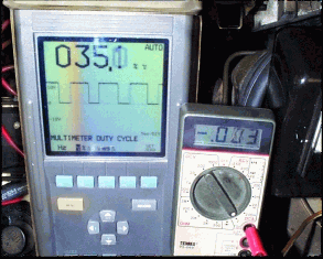
Figure 4: Duty cycle reading of 35% and an EHA current of -3ma.

Figure 5: Factory tool reading of cycle and EHA current.
A similar hook-up with an inexpensive ammeter can be connected to the idle control valve. The values change with this system on different vehicles, but monitoring current flow can show problems that cause the number one complaint I see ? intermittent stalling. The current usually runs from 600-700ma at idle. Adding A/C usually adds 50ma control. When the idle switch opens, the valve is held open at 800-900ma to prepare for sudden throttle release. The number one intermittent problem we see is caused by the over-voltage protection (OVP) relay. Watching the idle valve current allowed me to understand how the OVP can cause stalling.Since a disconnected idle valve limps home at a higher than normal rpm, I always found it hard to understand how removing the idle valve?s power could cause a stall. I finally saw it, though, while driving and monitoring the idle valve current. The normal current of 600-700ma dropped to 350-450ma and the idle dropped to about 450 rpm. A thump on the OVP relay caused the current, as well as the idle, to instantly jump to proper value. The current was being controlled not by the KE controller, but rather by the bad internal power feed connection of the OVP.
The OVP also totally fails or burns its fuse, killing all EHA current. This condition doesn?t affect a warm motor, as it should already be running closed loop at zero milliamps. But it causes most of the hard cold-starting problems. Watching the EHA current is a quick way to verify a good OVP relay. Since the ABS is also powered by the OVP relay (often by a separate circuit), a real quick diagnostic insight can be made by the combined symptoms of ABS light and hard cold starting.As these systems progressed, they were equipped with on-board self-diagnostics with memory and check engine lights. This "fourth window" is also accessible with regular shop electrical tools. In this case, I used a scope to verify the readings that I received from my impulse counter tool (see Figure 6) that is similar to the factory tool.

Figure 6: Impulse tool counter
This process of reading codes for these early systems works up to 1994 for all systems, and later on some systems. Basically, it will work up to OBD II systems, and applies to all systems, not just engine management systems. The code retrieval method is very simple. The communications take place over a single line on the appropriate diagnostic connector. On the car I used (a 1991 300TE), the connector (X11/4) is located next to the battery, next to the right side hood hinge.
The KE controller is accessed on data terminal #3. With the key on, engine off, self-diagnostics is activated by grounding the #3 pin for two to four seconds. Once this takes place, the control unit transmits the codes by itself, grounding the #3 terminal. (Remember that all systems work the same; all you need is a directory of which pins to activate and the code table to interpret.)
The impulse counter makes life easy by counting up some high numbers. In the scope pattern in Figure 7, I connected the scope negative lead on the battery positive and the positive lead in the #3 pin.

Figure 7: Code 7 reading.
I attached a jumper ground for three seconds and the control unit grounded the pin seven times, which could easily be counted. This was done again and code 13 was read, again and code 14 was read, and again and code 27 was read. If you are using the scope to read this, the time scale must be appropriate to get the whole thing, as every further activation moves on to the next code. They are listed one at a time until they are repeated. This can be done over and over. Each time the pin is grounded for two to four seconds, the next code is communicated by the control unit, grounding out the code number in "blinks." An LED can also be used to see a "blink" for counting. Once all codes are read, they can be erased by holding the jumper to the appropriate pin for six to eight seconds. After this is done, another activation with a two- to four-second ground will read the next code, and a further six- to eight-second ground pulse will erase it. This is continued until all codes have been read and erased. This will be shown by the final code of "one blink."
With the development of self-diagnostics in the late '80s, came the ability to receive fault codes, view actual data, activate elements and eventually change programming. The car mentioned above can be viewed and have its codes read by common shop tools. Reading actual data will require a factory scanner or a clone. Version coding and changing of adaptations has been out of reach without the factory tool HHT. Probably the most crucial place this has affected us has been in our body shop. All the air bag modules since 1995 need to be version coded, requiring a trip to the dealer. It is claimed that one aftermarket scanner?s newest version will now do version coding, reset adaptation values and even do some data graphing. I am eager to check this out as my plans were forming to spend the big bucks on the Mercedes-Benz tool, Star Diagnosis, which is now available in some form to independents.
I recently had the pleasure to witness the testing of a 1998 GM product EVAP system with the Tech 2. The presenter showed how an OBD II EVAP monitor could be initiated using a "Service Bay Test" function. The tool also could manually do testing by activating the vent valve and purge valves. The Mercedes-Benz EVAP system is similar but has no similar way of doing a service bay test using any of the aftermarket scanners. I couldn?t find anyone who knew whether or not the Star Diagnosis tool could perform such tests. Without the ability to do those tests (especially if the manufacturer can), we need more than tools to figure them out at times. A recent case shows the latest tool: The internet. A case in point involves the iATN. A C280 came in with the "Check Engine" light on. The fault code indicated EGR low flow. We reset the light and checked that the vacuum was going to the EGR valve. The light was back on in a week. We replaced the EGR valve, thinking that it was intermittently sticking. Again, the light came back on in one week. While surfing iATN archives for a separate problem, I came upon the fix. It was a carboned-up port (see Figure 8).
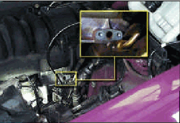
Figure 9: Restriction at intake manifold side is difficult to access.
The value to the "archive fix" was that it pointed out that the restriction was at the intake manifold side. From Figure 9, one can see the location is difficult. From Figure 10, one can see that the blockage has been removed. Once there, it became evident that this wasn?t carbon from the EGR, but rather PCV vapors from the intake coating the hot pipe inlet.We have now added a job to our 30K services on the M104 motor. We open the steel line at the EGR valve and feed in a long section of speedometer cable. We spin the cable with a drill motor and run it through the whole tube into the intake manifold. This is a simple operation, yet it prevents having to unbury the actual fitting when it?s really plugged.
My thanks to the iATN and the unknown author.
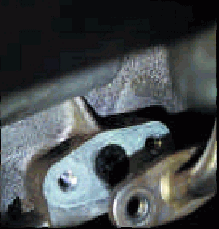
Figure 8: Carboned up port.
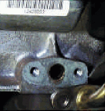
Figure 10: Blockage removed from port.
PeachParts would like to thank Steve Brotherton for sharing this excellent article with us.
CategoryDiy